Featured Article
Super-resolution microscopy was developed to address limitations in confocal microscopy, such as lateral resolution. This article describes a simple optical redesign that converts a standard confocal microscope to a super-resolution microscope.
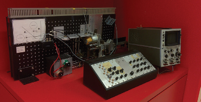 Figure 1 – One of the first confocal microscopes, developed in the laboratory of Professor G.J. Brakenhoff in Amsterdam. In the late 1980s, Erik Manders helped to develop this microscope as a student project. RCM is based on this technology.
Re-scan confocal microscopy (RCM) from Confocal.nl is based on the standard confocal microscope1 (Figure 1). The most important property of the confocal microscope is its axial resolution (optical sectioning), which allows 3-D imaging. Under certain conditions, the confocal microscope also offers improved lateral resolution.
A confocal microscope is a point scanning technique, that is, a focused laser beam is directed into the sample, exciting fluorescent molecules. Light emitted by these fluorescent molecules is collected by the objective and directed toward a detector. A pinhole at the front of the detector improves axial resolution by filtering out-of-focus light from the sample, which is essential for 3-D imaging. The pinhole also reduces the detection efficiency of off-axis light, improving lateral resolution. However, this can only be achieved with an extremely small pinhole, thus compromising signal-to-noise ratio. Confocal images recorded with small pinholes are sharper but noisier. Most biologists therefore opt for relatively large pinholes, sacrificing resolution for improved signal-to-noise ratios.
Loss of information and other limitations of using a pinhole in confocal microscopy were described in the 1980s. The pinhole obstructs unnecessary light and admits light when needed. All light passing through the pinhole is detected by the same detector. However, the position inside the pinhole where the light passes the pinhole is lost forever. Light traversing the center of the pinhole provides the same point-detection response as light that traverses the left-hand side in the periphery of the pinhole. Sheppard demonstrated that this irreversible loss of information leads to reduced resolution, and Enderlein described a method to restore this information by using a camera behind the pinhole instead of a point detector. Using a complex computer algorithm, Enderlein was able to obtain images with improved resolution.
Re-scan confocal microscopy
RCM does all the calculations of the Enderlein method, not with a computer but in a pure optical way.2 The microscope has a scanning unit (two galvo-driven orthogonal mirrors), identical to the standard confocal microscope, that directs the laser light toward the sample and directs the emitted light from the sample back toward the pinhole. Where the standard confocal microscope has a point detector (photomultiplier tube of a more advanced gallium arsenide phosphide or hybrid detector), the Re-scan has an additional scanning unit, called the re-scanner (Figure 2). This directs the emission light that passes the pinhole toward a sensitive camera in a scanning manner. The movements of the scanner and re-scanner are highly synchronized—they move with the same frequency, phase, and angular amplitude. Thus, while the focused laser beam “reads” the sample, the focused emission beam “writes” the image of the sample on a camera chip.
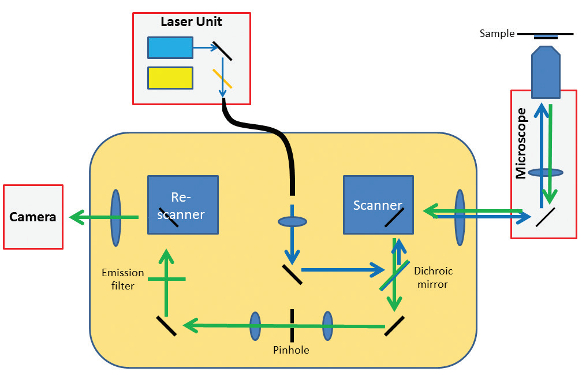 Figure 2 – Optical design of RCM.
At this point in its development, the method did not yet provide additional resolution. The optical system was still diffraction-limited—the image was “written” on the camera with a blurry spot according to the point-spread function (PSF) of the optical system. Resolution was limited by the thickness of the optical pencil (PSF) that “writes” the image. To write an image with improved resolution, the optical pencil needed to be sharper. Unfortunately, Abbe’s Law precluded sharpening the pencil, as it is defined by the optics.
The developers discovered a solution to the problem once they realized that RCM uses both optical and mechanical imaging. For example, the final magnification of the image is also defined by the angular amplitudes of the scanning mirrors. While Abbe’s Law makes it impossible to sharpen the pencil, a larger picture can be created with the same pencil by doubling the angular amplitude of the re-scanner. In this way, the size of the image written on the camera chip is doubled, writing is still done with the same blurry spot, and the final image becomes relatively sharper. This improvement in resolution comes at a price, however. Since the optical pencil moves so rapidly over the image plane of the camera, some motion blur is introduced. This motion blur factor (B) is directly related to the ratio (M) of the angular amplitude (sweep) of the scanner and re-scanner as:
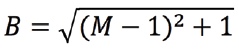
Therefore, for a double sweep (M = 2), the image becomes √2 times blurrier, but, since the image is two times larger, the final image becomes relatively sharper by a factor of √2. This is key to improved resolution (see www.confocal.nl for an explanation of the RCM principle).
Proof of principle
 Figure 3 – Cells with fluorescently stained cytoskeleton.
After the development of this basic idea, De Luca, Breedijk, and Manders sketched optical configurations and built the first prototype of the optical table. By doubling the sweep factor, the optical resolution dropped from 240 nm to 170 nm—exactly a factor of √2 (Figure 3). A smaller prototype was constructed next. The RCM was modified for multicolor imaging. As a result of the microscope’s four-times-higher signal-to-noise ratio, images were crisper (Figure 3). For biologists, improved signal-to-noise is important since fluorescent samples are sometimes very weakly labeled.3–5
From prototype to start-up
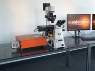
 Figure 4 – Complete RCM system consisting of a microscope body, RCM scanning unit and sensitive camera.
In February 2016 Confocal.nl BV was founded as a spin-off of the University of Amsterdam. Before bringing RCM to market, its optics, mechanics, and electronics were redesigned based on the original concept and prototypes (Figure 4).
Simplified technology based on redesigned optics6 make RMS an effective technique for procedures such as deep-tissue imaging. Future applications include use in research laboratories for clinical and biomedical research.
References
- Brakenhoff, G.J.; Blom, P. et al. Confocal scanning light microscope with high aperture immersion lenses. J. Microsc. 1979,117, 219–32.
- De Luca, G.M.R.; Breedijk, R.M.P. et al. Rescan confocal microscopy: scanning twice for better resolution. Biomed. Optics Express 2017, 4(11), 2644–56.
- Schouten, M.; De Luca, G.M. et al. Imaging dendritic spines of rat primary hippocampal neurons using structured illumination microscopy. J. Vis. Exp. 2014, May 4(87).
- De Luca, G.M.R. and Manders, E.M.M. Rescan confocal microscopy (RCM). In Super-Resolution Imaging in Medicine and Biology, Chapter 7; Diaspro, A. and van Zandvoort, A.M.J., Eds.; Taylor & Francis Group LLC: New York, N.Y., 2017.
- De Luca, G.M.R.; Breedijk, R.M.P. et al. Rescan confocal microscopy (RCM) improves the resolution of confocal microscopy and increases the sensitivity. Meth. Appl. In. Fluorescence, in press.
- De Luca, G.M.R.; Desclos, E. et al. Configurations of the Re-scan confocal microscope (RCM) for biomedical applications. J. Microsc. 2017; in press.
Erik Manders is associate professor, Innovative Microscopy Lab of the Swammerdam Institute for Life Science, University of Amsterdam, Spui 21, 1012 WX Amsterdam, The Netherlands; tel.: +31 (0) 20 525 9111; e-mail: [email protected], and scientific director of Confocal.nl, www.confocal.nl. Peter Drent is CEO of Confocal.nl. Ronald Breedijk works in the Innovative Microscopy Lab, University of Amsterdam.