In inductively coupled plasma (ICP) spectroscopy, clogged nebulizers and shortened torch life can cause a significant source of random and systematic errors in the overall measurement of a sample, resulting in interrupted runs, signal drift, and greater signal interferences. These errors are magnified when dealing with samples with complex matrices, which are more the norm than the exception in ICP spectroscopy.
This article discusses factors to consider for optimizing an ICP sample introduction system to alleviate any errors that can be caused from difficult samples, such as high total dissolved solids (TDS) and volatile organics.
ICP systems
The concentration of an element within a sample can be measured by either ICP mass spectrometry (ICP-MS) or ICP optical emission spectrometry (ICP-OES). In ICP-MS, the measurement of concentration is correlated to the mass of the element, and in ICP-OES, the measurement of concentration is correlated to the optical emission of the element.
An ICP-MS system consists of a sample introduction system, an interface region, a vacuum region, a lens system, a mass spectrometer, a vacuum system, a detector, and a data handling system. An ICP-OES system consists of a sample introduction system, an interface region, an optical chamber, an optical emission spectrometer, a detector, and a data handling system.
In both ICP-MS and ICP-OES systems, the sample introduction system consists of a nebulizer, a spray chamber, and an ICP torch.
To analyze a liquid sample or a dissolved solid sample, the sample is pumped into the nebulizer to produce an aerosol. The aerosol is filtered in the spray chamber so that only the smallest aerosol droplets are introduced into the plasma. The plasma is generated by passing argon through the ICP torch surrounded by a radiofrequency coil. In the plasma, the aerosol is heated to a gas.
In the ICP-MS system, atoms are generated from the gas and travel through the plasma, absorb energy, and turn into excited atoms and ions. The ions then exit the sample introduction system into the interface region, the vacuum region, and the lens system. The vacuum system focuses the ions into the mass spectrometer, which separates the ions on the basis of mass, and the element type of the ions is detected and analyzed based on mass by the data handling system.
In the ICP-OES system, atoms are generated from the gas, travel through the plasma, absorb energy, and are excited. When the excited atoms return to a low energy position, emission rays or spectrum rays are released into the interface region and are collected with a lens or mirror into the optical chamber. In the optical chamber, the emission rays are separated into the different wavelengths, exit the optical chamber, and are measured in the optical emission spectrometer. The element type is detected and its content determined based on the intensity of the emission rays, and analyzed by the data handling system.
Optimization methods
In order to achieve the best ICP performance with a particular sample matrix, the ICP operating parameters must be optimized, in addition to selecting a proper sample introduction system. For samples high in TDS, it is essential that a nebulizer resistant to salting and a large-bore injector are paired with an argon humidifier, in addition to a baffled cyclonic spray chamber to prevent large droplets from reaching the ICP torch. With volatile organic samples, a chilled baffled cyclonic spray chamber and small-bore injector combine to reduce the solvent load and improve plasma stability. A demountable ICP torch can lower the replacement torch costs for both high TDS and organic applications, which often cause a short torch life due to devitrification or cracking of the quartz.
Humidifer
In the nebulizer, dry argon is used to generate an aerosol and transport the sample to the ICP. With samples containing high amounts of TDS, there is a greater likelihood of salt deposits forming at the tip of the nebulizer and injector. These salt deposits can result in failed analysis due to a drift in signal or an extinguished plasma. Adding moisture to the nebulizer gas before it comes into contact with the sample lessens the chances of salt deposits forming.
The Elegra argon humidifier from Glass Expansion adds moisture to the nebulizer gas as it flows through it at atmospheric pressure, and a dual-channel Elegra argon humidifier adds moisture to the nebulizer gas and an auxiliary or dilution gas.
The performance of the Elegra argon humidifier was evaluated in a nebulizer stress test. In the test, 25% NaCl solution was aspirated continuously with no rinsing. The nebulizer gas flow with and without the Elegra argon humidifier was monitored. Without the Elegra argon humidifier, the nebulizer was completely clogged after only 5 minutes. In contrast, the same nebulizer with the Elegra argon humidifier held a relatively constant gas flow throughout the entire test for over 30 minutes (see Figure 1).
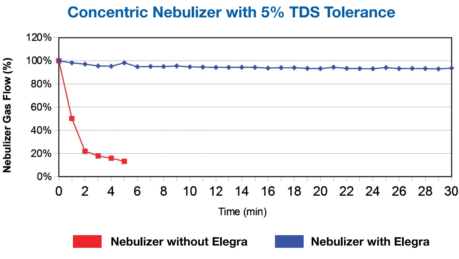 Figure 1 – Nebulizer high TDS stress test. Source: Glass Expansion Inc.
The dual-channel Elegra argon humidifier provides the ability to humidify both the nebulizer gas and an auxiliary or dilution gas, and prevents nebulizer and injector blockage due to salt buildup. In ICP-MS, high TDS samples can be diluted in the gas phase to prevent the rapid buildup of salt deposits on the nebulizer and interface cones, which would otherwise result in signal drift and the need for frequent cleaning. The additional humidification of the dilution gas results in a more robust plasma.
Spray chamber
The purpose of a baffled cyclonic spray chamber is to remove droplets >8 μm in diameter produced by the nebulizer and prevent them from reaching the ICP torch.
Maintaining a certain temperature affects the performance of the spray chamber. Cooling the spray chamber reduces oxide and polyatomic interferences, and decreases the volatility of solvents so that a stable plasma is sustained. Heating the spray chamber results in higher sample transport and enhanced sensitivity. Therefore, the ability to maintain a constant and stable spray chamber temperature is key for optimum spray chamber performance.
The IsoMist XR (Glass Expansion) maintains the temperature of a spray chamber without the need for a bulky chiller, liquid coolant, or complex coolant tubing, and without icing-up of the spray chamber. The temperature of the spray chamber is maintained in a controlled temperature range of –25 to +80 °C in increments of 1 °C.
Figure 2 shows the long-term signal intensity achieved with the IsoMist XR held at a constant temperature compared to a conventional cyclonic spray chamber. The results show that maintaining a constant temperature with the IsoMist XR significantly enhances long-term stability of the ICP signal intensity, resulting in improved analytical reproducibility and accuracy. Maintaining a stable ICP signal with the IsoMist XR also increases throughput and lowers operating costs by reducing the need to rerun samples should a QC check drift outside the acceptable range.
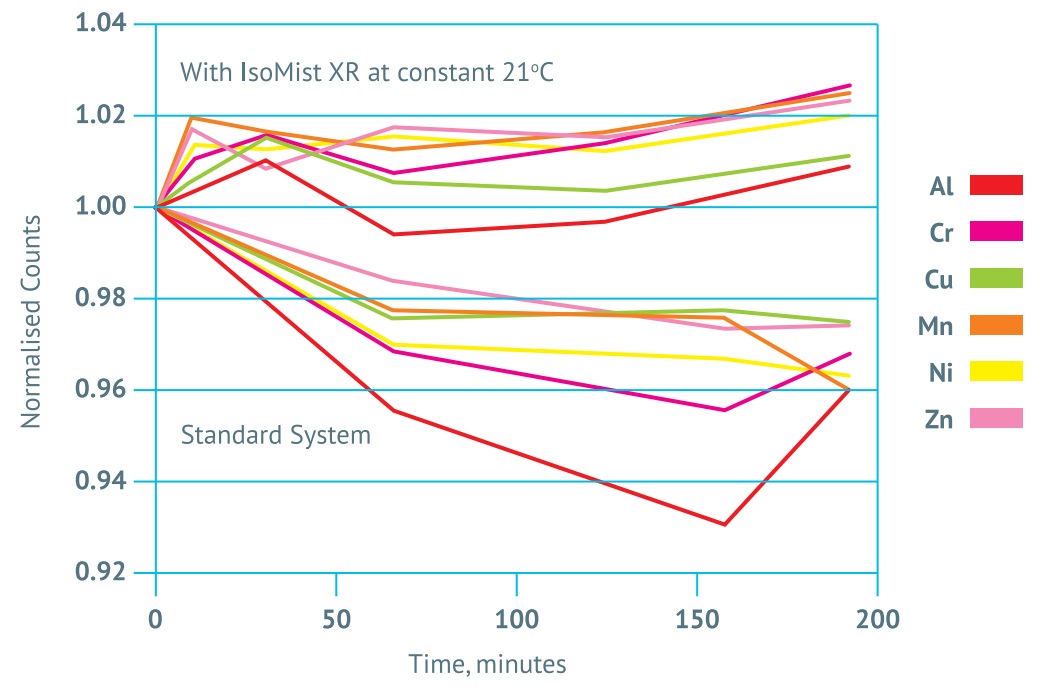 Figure 2 – Effects of IsoMist XR on signal stability at ambient temperature. Source: Glass Expansion Inc.
IsoMist performance was evaluated for the reduction of oxide interferences. Use of the IsoMist XR spray chamber at subambient temperatures decreased the amount of water vapor transferred to the plasma, resulting in reduced oxide formation and polyatomic (ArO, ArOH) interferences.
Figure 3 shows the effect of IsoMist XR temperature on the ICP/MS oxide ratio obtained on a PerkinElmer Elan ICP/MS. A temperature between 1 and 4 °C provides the optimum oxide ratio. Lowering oxide formation in the plasma translates to fewer interferences, improving accuracy and detection limits.
 Figure 3 – Effects of IsoMist XR temperature on ICP/MS oxide ratio. Source: Glass Expansion Inc.
The performance of the IsoMist was evaluated in the analysis of volatile organic solvents. These are challenging due to their high transport efficiency to the plasma, which creates an excessive load, resulting in plasma instability or cessation. One of the most difficult and commonly analyzed solvents is light naphtha. The IsoMist XR was used in combination with a Thermo iCAP 6500 Duo ICP-OES for the direct analysis of naphtha, without dilution. Figure 4 shows that by setting an IsoMist XR temperature of –25 °C compared to –10 °C, higher intensities are achieved for every wavelength measured.
 Figure 4 – Effect of IsoMist XR temperature on signal intensity in naphtha. Source: Glass Expansion Inc.
The sensitivity of many analyses can be enhanced by operating the spray chamber at elevated temperatures. To evaluate the effect of IsoMist XR temperature on the accuracy of precious metal measurements, a solution of Pt was analyzed at a range of temperatures and compared to the Pt concentration determined gravimetrically. Figure 5 shows that the Pt concentration is closer to the gravimetric or true value at a temperature of 40 °C.
 Figure 5 – Effect of IsoMist XR on measurement accuracy. Source: Glass Expansion Inc.
Among other benefits, the IsoMist XR has been shown to lower detection limits at a subambient temperature by reducing background and yielding a more robust and higher-temperature plasma (Glass Expansion Newsletter, June, 2017).
Injector
Selecting a larger-bore injector (>2.00 mm) slows the buildup of salts at the injector tip and enhances nebulizer operation. A constant bore injector is less susceptible to clogging than an injector that is tapered near the orifice. Tapered bore injectors with the taper moved away from the tip also reduce the likelihood of clogging. For organic solvents, a small-bore injector (<1.5 mm) helps to reduce excessive loading and improve plasma stability.
ICP torch
With high TDS samples, the combination of high temperature and salt deposits causes an ICP quartz torch outer tube to devitrify. For organics, the combination of carbon buildup and a higher RF power can result in a premature failure of the quartz outer tube. When a single-piece torch is used, it must be replaced when only the outer tube suffers from devitrification.
The Glass Expansion D-Torch provides an alternative to the single-piece torch. It incorporates a ceramic intermediate tube and an outer tube that can be replaced when failure occurs due to devitrification or fracture, rather than having to replace the entire torch. For really nasty samples, the quartz outer tube can be replaced with one made of ceramic, a material that does not suffer from devitrification or fractures, and typically lasts for years. Table 1 shows there is no degradation in performance when using the ceramic outer tube in comparison to the standard quartz torch.
Table 1 – Detection limit comparison: Ceramic D-Torch and standard quartz torch*
* Data taken from Thermo Fisher Scientific Technical Note #43202. Source: Glass Expansion.
Conclusion
For best performance of an ICP system, it is essential to choose the right sample introduction system components to alleviate any errors that may be caused by the introduction of high TDS samples and organic solvents. For more information, visit http://www.geicp.com.
Lina Genovesi, Ph.D., JD, is a technical, regulatory, and business writer based in Princeton, NJ, U.S.A.; e-mail: [email protected]; www.linagenovesi.com