Introduction
With the recent implementation of USP Chapters <232>, <233>, and ICH Q3D Step 4 guidelines for the measurement of elemental impurities in pharmaceutical materials, it’s extremely important that the plasma spectrochemical instrumentation used is kept in good working order to maximize performance and productivity.1 This is particularly the case with ICP-MS, one of the recommended techniques, which has unparalleled multielement detection capability, but in the hands of a novice or inexperienced user, can generate erratic and imprecise results, unless the instrument is maintained on a regular basis. For that reason, it requires a certain level of operator competence and expertise to fully understand when a problem arises so preventative action can be taken.
Benefit of routine maintenance in ICP-MS
The fundamental principle of ICP-MS, which gives the technique its unequalled isotopic selectivity and sensitivity, also unfortunately contributes to some of its weaknesses. The fact that the sample “flows into” the spectrometer and is not “passed by it” at right angles, such as flame AA and radial inductively coupled plasma-optical emission spectroscopy (ICP-OES), means that the potential for thermal problems, corrosion, chemical attack, blockage, matrix deposits, and drift is much higher than with the other atomic spectrometry (AS) techniques. However, being fully aware of this fact and carrying out regular inspection of instrumental components can reduce and sometimes eliminate many of these potential problem areas. There is no question that a laboratory that initiates a routine maintenance schedule stands a much better chance of having an instrument ready and available for analysis whenever it is needed, compared to a laboratory that basically ignores these issues and assumes the instrument will look after itself.
The areas of the instrument that require inspection and maintenance on a routine basis include the following components:
- Sample introduction system
- Plasma torch
- Interface region
- Ion optics
The majority of imprecision problems in ICP-MS arise due to the potential of sample matrix depositing itself either in the nebulizer tips, the sample injector of the torch, and/or the interface cones. In this article, we will focus on the sample introduction system, and in particular how to maximize the efficiency of the peristaltic pump tubing, nebulizer, and spray chamber to deliver the sample aerosol to the plasma torch free of problems.
Sample introduction system
The sample introduction system, comprising the peristaltic/pneumatic pump, nebulizer, spray chamber, and drain system, takes the initial abuse from the sample matrix, and, as a result, is an area of the ICP-MS that requires a great deal of attention. So, let us now examine what kind of routine maintenance it requires.
Peristaltic pump tubing
The sample is pumped at about 1 mL/min into the nebulizer. The constant motion and pressure of the pump rollers on the pump tubing ensures a continuous flow of liquid into the nebulizer. However, over time, this constant pressure of the rollers on the pump tubing has the tendency to stretch it, which changes its internal diameter and, therefore, the amount of sample being delivered to the nebulizer.
Therefore, the condition of the pump tubing should be examined every few days, particularly if the laboratory has a high sample workload or if extremely corrosive solutions are being analyzed. The peristaltic pump tubing is probably one of the most neglected areas, so it is absolutely essential that it is a part of a routine maintenance schedule. Here are some suggested tips to reduce pump tubing-related problems:
- Manually stretch the new tubing before use.
- Maintain the proper tension on the tubing.
- Ensure tubing is placed correctly in the channel of the peristaltic pump.
- Periodically check the flow of sample delivery, and throw away the tubing if in doubt.
- Replace the tubing if there is any sign of wear.
- With high sample workload, change the tubing every day or every other day.
- Release pressure on the pump tubing when the instrument is not in use.
- Pump and capillary tubing can be a source of contamination.
- Pump tubing is a consumable item, so keep a large supply of it on hand.
A very useful tool to diagnose any problems associated with sample introduction is a digital thermoelectric flow meter. By inserting this device in the sample line, you always know the actual rate of sample uptake to your nebulizer. This enhances the day-to-day reproducibility of your results and reduces the need to repeat measurements due to a blocked nebulizer, worn pump tubing, or incorrect clamping of the pump tube. A commercially available digital thermoelectric flow meter is shown in Figure 1.
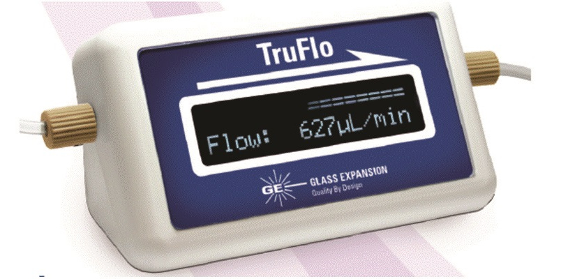 Figure 1 - A digital thermoelectric flow meter. (Courtesy of Glass Expansion Inc., Pocasset, MA.)
Nebulizers
The frequency of nebulizer maintenance will primarily depend on the types of samples being analyzed and the design of nebulizer being used. For example, in a cross-flow nebulizer, the argon gas is directed at right angles to the sample capillary tip, in contrast to the concentric nebulizer, where the gas flow is parallel to the capillary. This can be seen in Figures 2 and 3, which show schematics of a concentric and cross-flow nebulizer, respectively.
 Figure 2 – Schematic of a concentric nebulizer. (Courtesy of Meinhard Glass Products, Golden, CO.)
 Figure 3 – Schematic of a cross-flow nebulizer. (Courtesy of PerkinElmer Inc., Waltham, MA.)
The larger diameter of the liquid capillary and longer distance between the liquid and gas tips of the cross-flow design make it far more tolerant to dissolved solids and suspended particles in the sample than the concentric design. On the other hand, aerosol generation of a cross-flow nebulizer is far less efficient than a concentric nebulizer, and therefore it produces droplets of less optimum size than that required for the ionization process. As a result, concentric nebulizers generally produce higher sensitivity and slightly better precision than the cross-flow design, but are more prone to clogging.
So, the choice of which nebulizer to use is usually based on the types of samples being aspirated and the data quality objectives of the analysis. Whichever type is being used, attention should be paid to the tip of the nebulizer to ensure it is not getting blocked. Sometimes, microscopic particles can build up on the tip of the nebulizer without the operator noticing, which, over time, can cause a loss of sensitivity, imprecision, and poor long-term stability. In addition, O-rings and the sample capillary can be affected by the corrosive solutions being aspirated, which can also degrade performance. For these reasons, the nebulizer should always be a part of the regular maintenance schedule. Some of the most common things to check include:
- Visually check the nebulizer aerosol by aspirating water—a blocked nebulizer will usually result in an erratic spray pattern with lots of large droplets.
- Remove blockage by either using backpressure from the argon line or dissolving the material by immersing the nebulizer in an appropriate acid or solvent—an ultrasonic bath can sometimes be used to aid dissolution, but check with the manufacturer first in case it is not recommended. (Note: Never stick any wires down the end of the nebulizer, because it could do permanent damage.)
- Ensure that the nebulizer is securely seated in the spray chamber end cap.
- Check all O-rings for damage or wear.
- Ensure the sample capillary is inserted correctly into the sample line of the nebulizer.
- The nebulizer should be inspected every 1–2 weeks, depending on the workload.
The digital thermoelectric flow meter described earlier is also very useful to diagnose problems with the nebulizer, even if a self-aspirating nebulizer is being used. By placing the device in-line, you always know what your sample uptake is and can take immediate corrective action if there is any change. You can also record your sample flow in order to check that you are using the same flow from day to day.
If the flow meter indicates a blocked nebulizer tip, there are also nebulizer-cleaning devices available. Traditionally, if particulate matter from the sample lodges itself in the end of the nebulizer, cleaning wires or ultrasonic baths were the only way to remove the obstruction, which often resulted in permanent damage. These new cleaning devices are designed to efficiently deliver a pressurized cleanser through the nebulizer capillary to safely dislodge particle buildup and thoroughly clean the nebulizer, without fear of damage.
Spray chambers
By far the most common design of spray chamber used in commercial ICP-MS instrumentation is the double-pass design, which selects the small droplets by directing the aerosol into a central tube. The larger droplets emerge from the tube and exit the spray chamber via a drain tube. The liquid in the drain tube is kept at positive pressure, which forces the small droplets back between the outer wall and the central tube, where they emerge from the spray chamber into the sample injector of the plasma torch. Scott double-pass spray chambers come in a variety of shapes, sizes, and materials. Figure 4 shows a double-pass spray chamber coupled to a cross-flow nebulizer.
 Figure 4 – A double-pass spray chamber coupled to a cross-flow nebulizer. (Courtesy of PerkinElmer Inc.,Waltham, MA.)
The most important maintenance with regard to the spray chamber is to make sure that the drain is functioning properly. A malfunctioning or leaking drain can produce a change in the spray chamber backpressure, producing fluctuations in the analyte signal, resulting in erratic and imprecise data. Problems can also result from degradation of O-rings between the spray chamber and sample injector of the plasma torch. Typical maintenance procedures regarding the spray chamber include the following:
- Make sure the drain tube fits tightly and there are no leaks.
- Ensure the waste solution is being pumped from the spray chamber into the drain properly.
- If a drain loop is being used, make sure the level of liquid in the drain tube is constant.
- Check the O-ring or ball joint between spray chamber exit tube and torch sample injector—ensure the connection is snug.
- The spray chamber can be a source of contamination with some matrices/analytes, so flush thoroughly between samples.
- Empty the spray chamber of liquid when instrument is not in use.
- The spray chamber and drain should be inspected every 1–2 weeks, depending on workload.
Final thoughts
The subject is that routine maintenance cannot be overemphasized in ICP-MS. Even though it might be considered a mundane and time-consuming chore, it can have a significant impact on the uptime of your instrument. Read the routine maintenance section of the operator’s manual and understand what is required. It is essential that time be scheduled on a weekly, monthly, and quarterly basis for preventative maintenance on your instrument. In addition, you should budget for an annual preventative maintenance contract under which the service engineer checks out all the important instrumental components and systems on a regular basis to make sure they are all working correctly.
Note: This article highlights the importance of keeping the sample introduction clean, but for detailed information about maintaining the other instrumental components, please refer to the chapter on routine maintenance in the cited Ref. 1.
Reference
- Thomas, R.J. Measuring Elemental Impurities in Pharmaceuticals: A Practical Guide. CRC Press: Boca Raton, FL; ISBN 9781138197961, Feb 2018.
Robert Thomas, CSci, CChem, FRSC, is principal consultant, Scientific Solutions, 4615 Sundown Rd., Gaithersburg, MD 20882, U.S.A.; tel.: 301-570-2811; e-mail: [email protected]; www.scientificsolutions1.net