Defects in solids can arise due to chemical impurities introduced during production processes, material wear or corrosion. Scanning electron microscopes (SEM) equipped with a focused ion beam (FIB) are important tools in investigating the defect as shown in figure 1 (Li-battery cathode). For more than 15 years, ZEISS has been a leading developer of FIB-SEMs, aka Crossbeam instruments. In 2019 at Microscopy and Microanalysis in Portland, OR, ZEISS introduced several additions to their Crossbeam FIB-SEM family.

Figure 1: Scanning electron micrograph showing the microheterogeneity of a cathode of a lithium battery. The image is compiled by a raster scan of the region of interest. One can study the composition of the different features and relate these to function or defects.
“Crossbeam” refers to the special Design of the FIB-SEM instrument, see figure 2, where the SEM beam is vertical and the FIB at an angle of 54°. The target area of interest is placed at the crossing point of both beams. Other accessories such as energy dispersive or secondary ion mass spectrometers point towards the same focal point providing chemical analysis of the target.
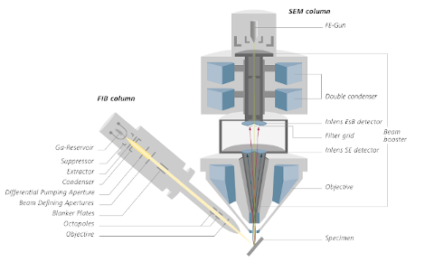
Figure 2: ZEISS Crossbeam 550 with a Gemini II SEM vertical assembly. The electron gun at the top is the source of the electrons, which traverse down through the column to the specimen (bottom). The focused ion beam (FIB) assembly is arranged at an inclination angle of 54°. An important design feature is that SEM and FIB beams point to the same spot on the sample facilitating analysis of objects down to the nm scale.
With the Crossbeam series, the microscopist has several options for probing or manipulating the sample. SEM and FIB can be used to image the spot. The ion beam can also be used to ablate the surface at specific locations to reveal the sub-surface microstructure of the sample. A third possibility is to perform an ion beam induced deposition from a small gas jet of precursor gas delivered by a gas injector. The gas molecules dissociate when hit by the ion beam to provide a thin layer on the surface, in a process that could be described as a local chemical vapor deposition (CVD).
At the M&M meeting in August 2019 in Portland OR, ZEISS extended the analytical capabilities of the Crossbeam product line by adding an accessory enabling Time of Flight Secondary Ion Mass Spectrometry (ToF-SIMS). With SIMS, one can identify the mass of the ions emitted as the target is sputtered by FIB. This can be particularly useful in determining the chemical composition of small defects.
Further, ZEISS introduced important improvements to its advanced 3D Tomography solution that facilitates generating images of serial sections of a volume of interest (VOI). These 2D images can then be stacked as pancakes to reconstruct the original 3D structure of the VOI. ZEISS advanced tomography solution now supports 3D crystallographical studies by Electron Backscatter Diffraction (EBSD) in a static geometry. Because the sample is not moved during the experiment, the thickness of the tomography slices can be controlled very precisely.
The Crossbeam line features a new, novel sample holder designed to facilitate the preparation of ultra-thin samples for detailed sample examination in STEM mode in the Crossbeam or in a separate dedicated TEM. The entire preparation process is easier. First, the navigation feature facilitates the location of the region of interest with a navigation camera located on the airlock. The Automated Sample Preparation feature facilitates the preparation of the lamella in the bulk according to a user-defined preparation protocol. Once this recipe has been programmed, it can be repeated for preparation of batches of specimens as required. The micromanipulator facilitates extracting the lamella from the bulk sample, which is then transferred to a TEM grid support for further thinning, and then analysis. Two SEM detector signals in parallel are used to monitor the lamella thickness and target precisely the region of interest during the thinning protocol.